
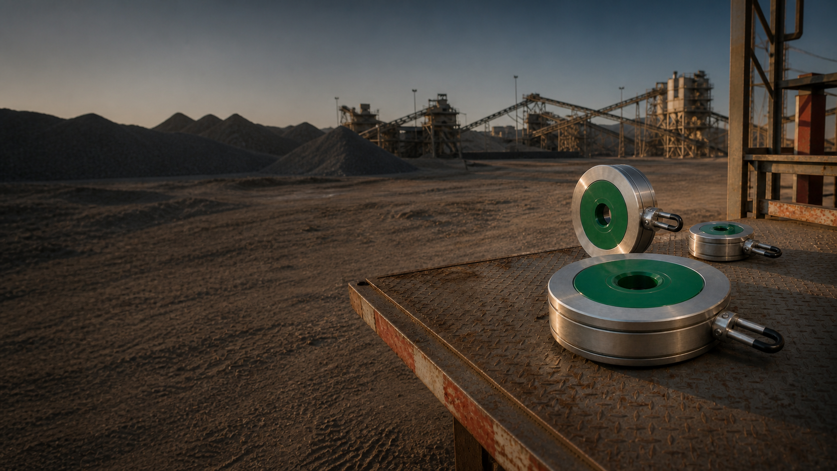


Reusable metal housing
Engineered to the selected size, pressure class and material specification.
MODULAR INLINE CHOKE · FIELD REPLACEABLE
A reusable severe-service housing with a replaceable jade ceramic flow element—engineered for slurry, tailings and corrosive process duty.
Retain the engineered pressure boundary.
Service only the component exposed to wear.
Return the choke to service without a rebuild cycle.
Configure, simulate and quote from one model.
THE MODULAR SYSTEM
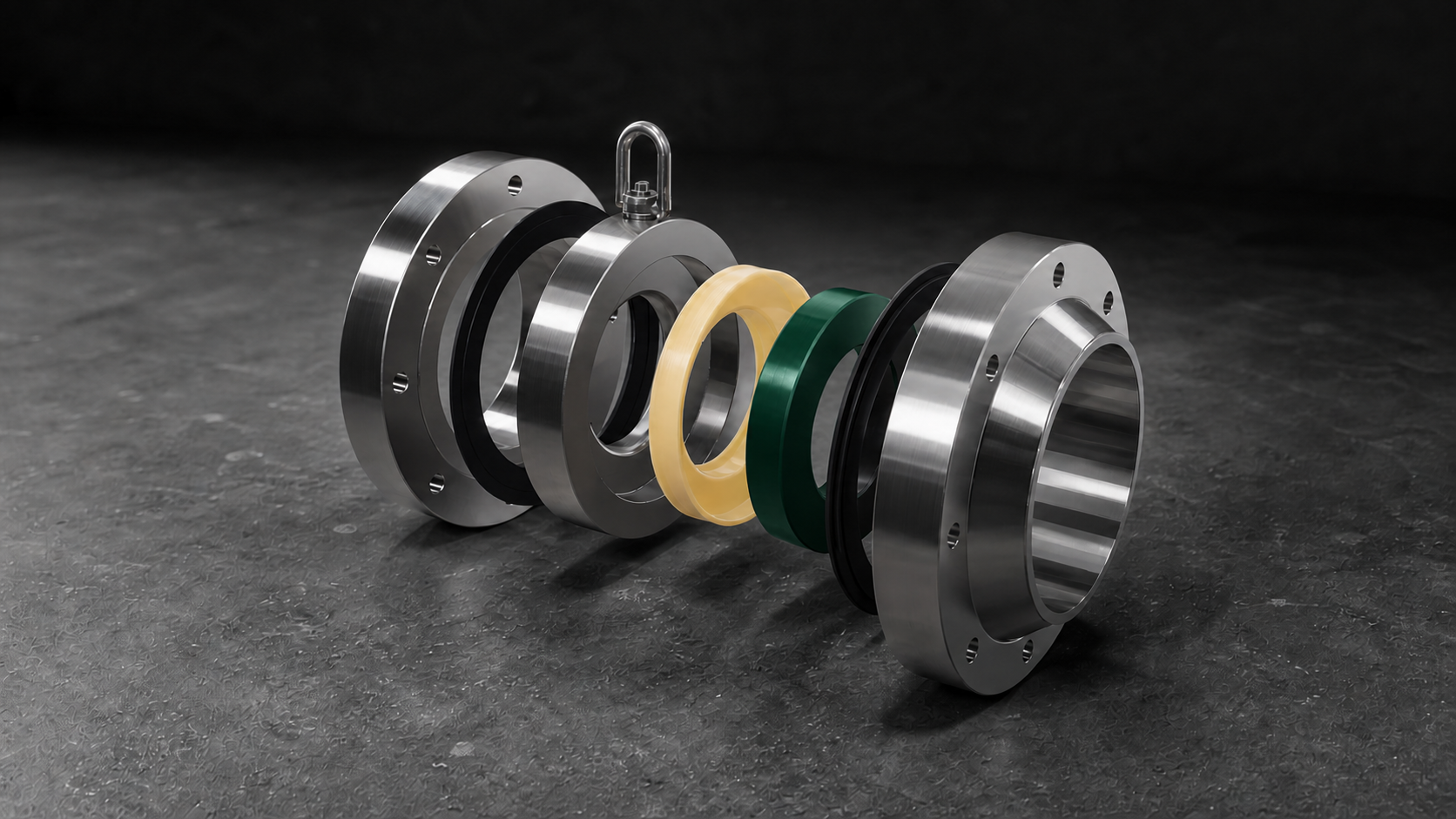
The housing stays in service. The ceramic flow element is selected for the duty, inspected and replaced when its service limit is reached.
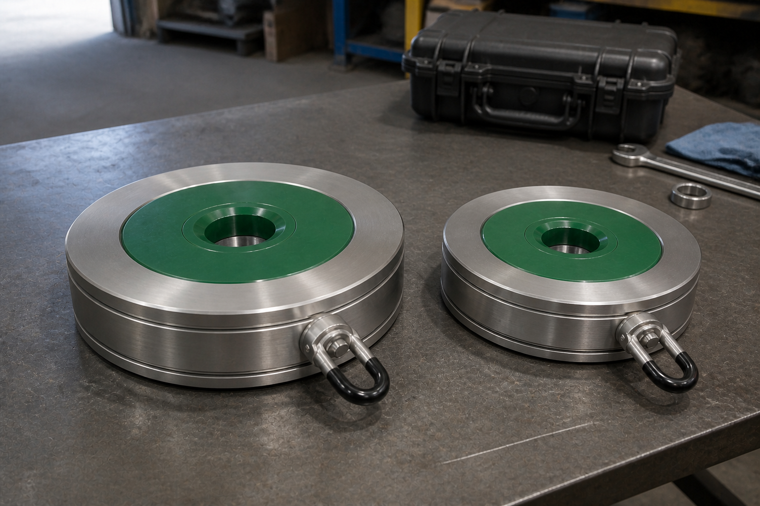
Engineered to the selected size, pressure class and material specification.
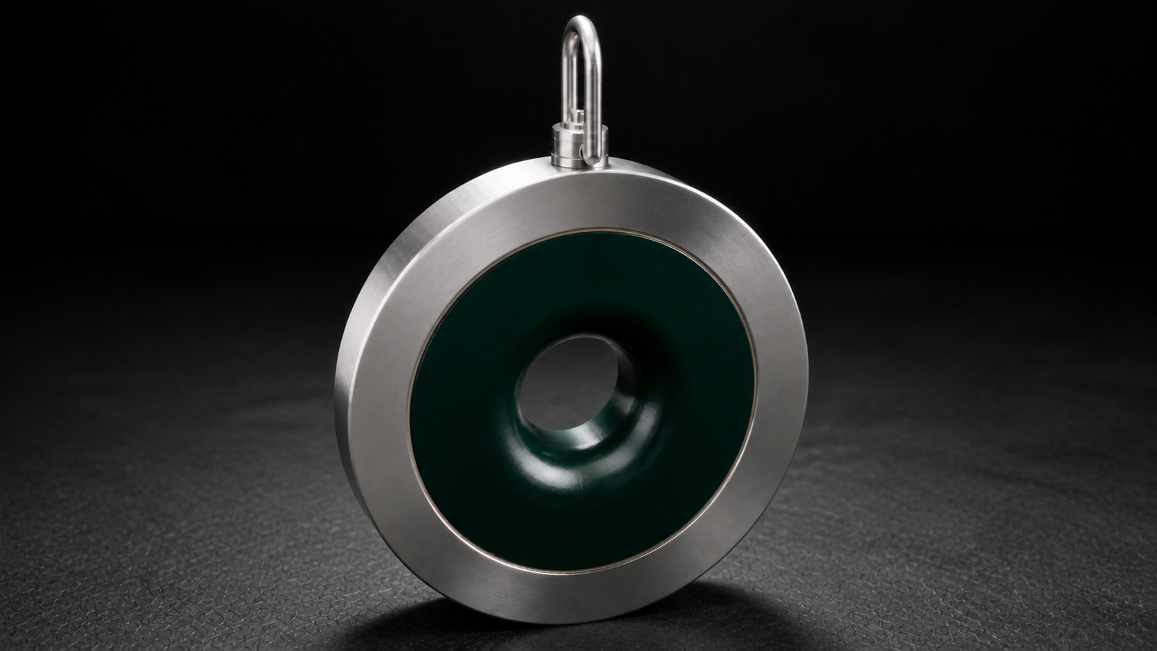
A replaceable severe-wear core with the bore configured for the process duty.
A controlled interface seats the ceramic inside the housing without an exposed gap.
Side-mounted lifting hardware supports safe movement of larger assemblies.
CONFIGURATION RANGE
Start with nominal size and pressure class, then connect housing material, ceramic system and bore geometry to the operating duty.
Fixed severe-service assembly sized to the selected piping and flange requirements.
Reusable housing with a field-replaceable ceramic wear package.
The ceramic flow path is configured around process conditions and review inputs.
MATERIAL SYSTEMS
Material selection remains connected to the same product configuration used for engineering review and quotation.
THE EXCHANGE SEQUENCE
See the field-oriented maintenance sequence: release the worn module, install the prepared replacement and close the reusable housing.
Open the reusable housing and remove the ceramic assembly from the service position.
Install the prepared module, close the assembly and return the choke to the line.
SERVICE MODEL COMPARISON
A direct architectural comparison between the ModFlowX modular service model and a conventional full-assembly maintenance path.
ENGINEERED ARCHITECTURE
Nominal size, pressure class, housing dimensions and ceramic bore remain connected from configuration through engineering review.
DIGITAL ENGINEERING
Upload a drawing, PDF, spreadsheet or field image. The portal organizes the project around the actual part, then carries the selected choke into 3D configuration and simulation.
MODFLOWX IN YOUR POCKET
Bring your files, explore the choke in 3D and send a quotation request. Use ModFlowX on your phone, tablet or in your browser.
Open in your browserAuthorized account required. Store availability varies by country and device.
Start with a photo, drawing or document.
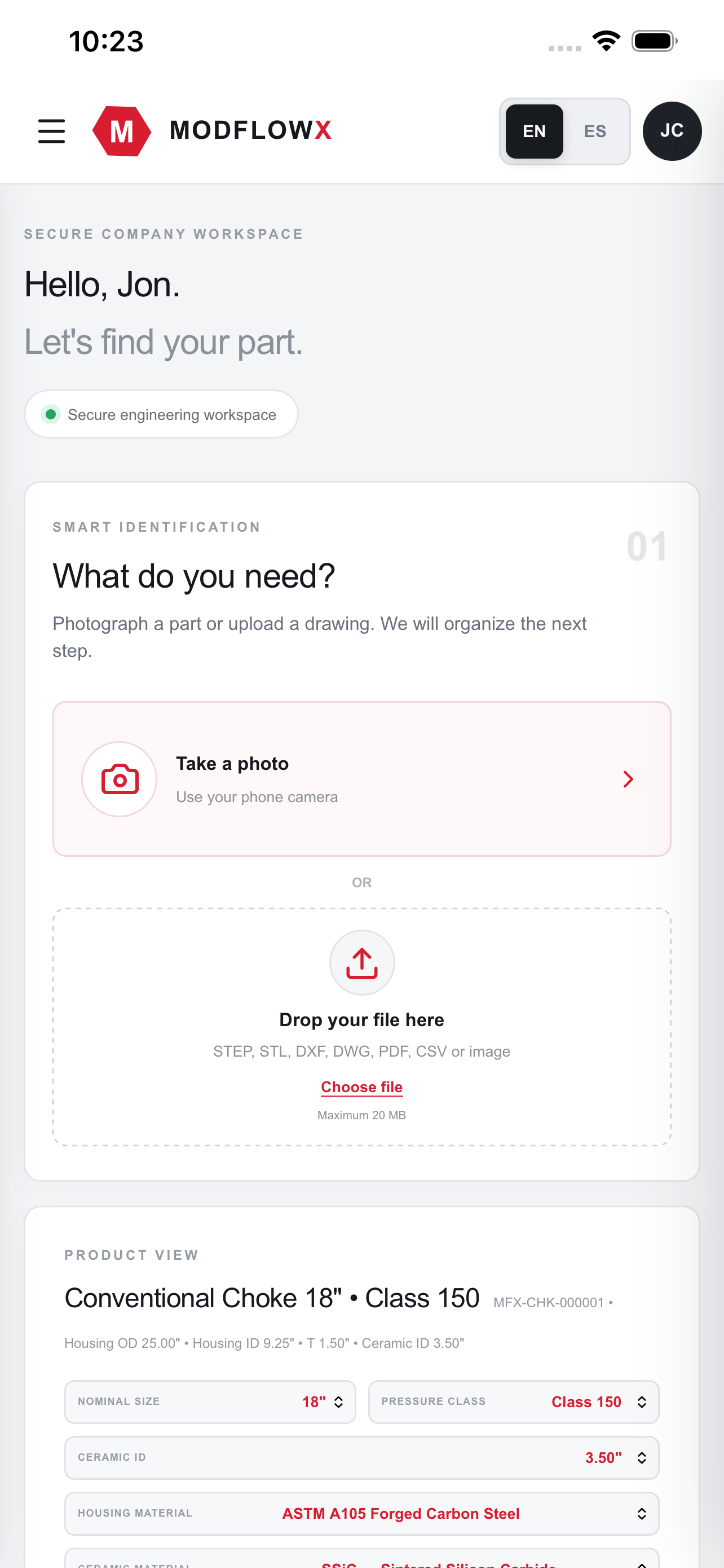
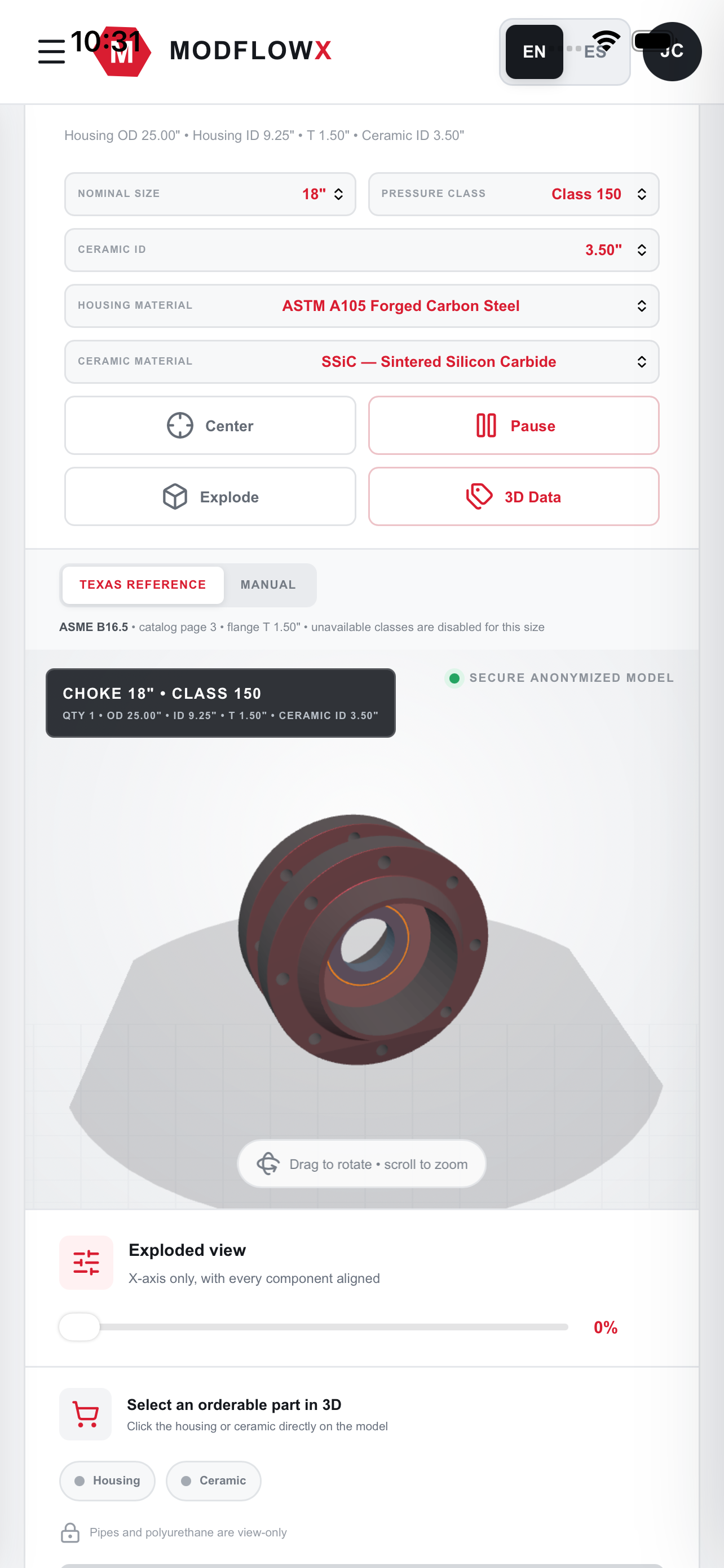
Review the housing, ceramic and selected dimensions.
Choose the components and send your requirements.
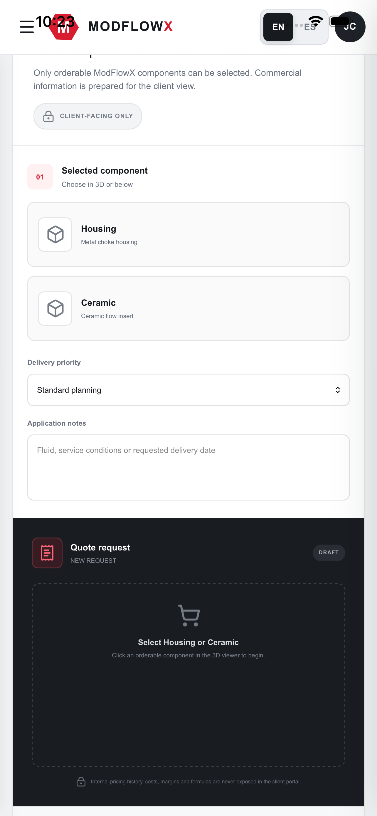
Store screenshots show an earlier interface. Screens and features may change. Extracted dimensions require review; a photo or material name alone does not establish remaining service life.
DESIGNED FOR SEVERE SERVICE
ABOUT MODFLOWX
ModFlowX develops next-generation flow-control systems for mining and energy applications. The company was created to make severe-service equipment more modular, faster to support and easier to maintain.
From ceramic design and 3D modeling to CFD, FEA, manufacturing and final packaging, each project follows one connected engineering workflow.
START WITH THE REAL PART
Configure a choke, upload project files or begin a customer quotation.